Howdy!
Welcome to the first of (hopefully) many blog posts about the Leonard Greenhouse Project, and how I plan to digitize it.
Some background and history for all of you. Greenhouses are typically used to extend the growing season, not necessarily to grow throughout the whole year. Though technically possible, most people opt for the former. Built in 1619 the first practical greenhouse was made by a Frenchman named Charles Lucien Bonaparte. The first American greenhouse was built by Andrew Faneuil in Boston in 1737. Now, 284 years later, I feel like we can do a little better. My father and I, (whose blog you can find at andyleonard.blog) will be attempting to digitize and modernize our greenhouse. So far we’ve already managed to integrate several different aspects of software development, data management, microcomputers, and good old backyard Redneckery.
However, we have to start somewhere. This is that somewhere:
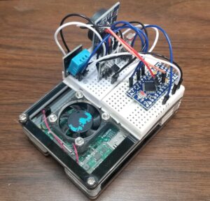
I present to you: the Greenhouse Telemetry Unit or GTU.
It is an Arduino Pro Mini, connected to four individual sensors, all mounted on a Raspberry Pi 3B. All of which I will delve into in greater detail below.
This series will be broken down into three sections: the Sensor Package, the Arduino, and the Pi.
Let’s start from the ground up, parts for the sensor package for the Arduino.
18B20 Digital Temp
This sensor is used to give me super accurate temperature readings, which is relatively important in a greenhouse. On average, most plants will die if the ambient temperature drops below 42 degrees Fahrenheit. This sensor module can take anywhere from 3 volts up to 5.5 volts. It has an absolute temperature range of -55°C to +125°C, which is to say those are the temperatures the device can physically withstand before melting or turning into a slushie. Its temperature reading range (IF I’m reading the datasheet right) is between -10°C to +85°C. I almost didn’t include this sensor, then I read the datasheet for the DHT11 sensor and realized exactly why I need it.
DHT11 Temperature and Humidity Sensor
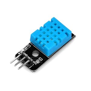
This sensor is the reason I included the accurate temperature sensor. It gives me the less accurate temperature, which I completely disregard, however, it gives me humidity, something that’s very important to greenhouses, as my mother insists. Apparently, if the ambient humidity drops below a range, it can cause the plants to look dry and become more susceptible to disease. While the datasheet for the DHT11 doesn’t specify the absolute maximum tolerances for the device, I can assure you setting it on fire or using it to read the temperature in the Arctic ice is not within tolerance. The measurement range for temperature (which is useless to me) is 0 to 50 °C. However, the relative humidity measurement range is 20% to 90%RH. For those of you seeing that and thinking “Well what if it drops below 20%? How are you going to read it?”, I say, why are you reading humidity on the Bonneville Salt Flats with a $5 sensor? In all honesty, this is extremely useful data for a greenhouse, where, in the event of a humidity reading of below 20%, you have much, much bigger problems. Now, all I need is to be able to see how much light is in the greenhouse.
Elegoo Photo Resistor (sometimes called LDR or ‘Light Dependent Resistor’)
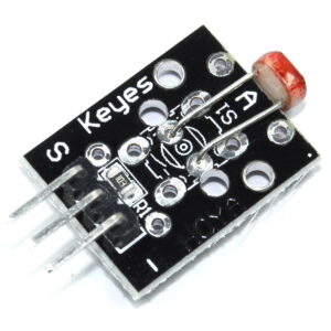
The Photo Resistor was included to provide very little data (compared to the other sensors) on the basis that it will be added to and compared to other data collected by the Greenhouse Telemetry Unit. For instance, say I wanted to do a hysteresis measurement on how the amount of light entering the greenhouse is affecting the temperature, and how quickly it’s doing so. That’s the sort of thing this sensor would come in handy for, though that use case is further down the line, and in a more in-depth area than this post can cover. So now we have all the right pieces to collect data, but in severe cold and severe heat, the Arduino’s internal clock has been known to suffer, same for the Pi. How can we be sure our data is up to date and on time?
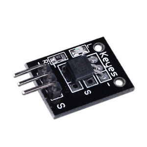
DS-3231 RTC ‘Real-Time Clock’ Module
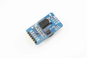
The DS-3231 RTC is the answer to that question. It’s an extremely accurate I2C real-time clock. It has an internal temperature-compensated crystal oscillator or TCXO for short. Included in the sensor is a battery slot to maintain accurate time when the main power to the device is interrupted. This is probably one of my favorite sensors since it’s just so interesting to me. But I won’t bore you with my geeky interests. Again, don’t light it on fire, don’t aim a jetting CO2 canister at it, but other than that it can operate in a range of 0°C to +70°C. The datasheet for this is really in-depth as well, giving temperatures at which you can store it, temperatures at which the solder will melt, and the junction temperature maximum. It can handle anywhere from .3 volts to +6 volts, making it compatible with just about any micro-computer or micro-controller.
Now, the code to get all these running. First, you want to install the Arduino IDE, something I will cover at a later date in a later blog, then open the IDE. Encapsulated here is the code you want to input into your IDE:
#include "DHT.h"
#include <OneWire.h>
#include <DallasTemperature.h>
#include <Wire.h>
#include "RTClib.h"

#define ONE_WIRE_BUS 4  // Data wire is plugged into digital pin 4 on the Arduino
#define DHTPIN 2     // Digital pin connected to the DHT sensor
#define DHTTYPE DHT11   // DHT 11

DHT dht(DHTPIN, DHTTYPE);
OneWire oneWire(ONE_WIRE_BUS);  // Setup a oneWire instance to communicate with any OneWire device
DallasTemperature sensors(&oneWire);  // Pass oneWire reference to DallasTemperature library
RTC_DS3231 rtc;

// RTC Clock Code
char daysOfTheWeek[7][12] = {"Sunday", "Monday", "Tuesday", "Wednesday", "Thursday", "Friday", "Saturday"};

// Photo Resistor Code
int sensorPin = A0;   // select the analog input pin for the photoresistor

void setup() {

  // DHT Code

  sensors.begin();  // Start up the library
  Serial.begin(9600);
  Serial.println(F("DHTxx test!"));

  dht.begin();

  // RTC Code

  if (! rtc.begin()) {
    Serial.println("Couldn't find RTC");
    while (1);
  }

  if (rtc.lostPower()) {
    Serial.println("RTC lost power, lets set the time!");

  // Comment out below lines once you set the date & time.
    // Following line sets the RTC to the date & time this sketch was compiled
    rtc.adjust(DateTime(F(__DATE__), F(__TIME__)));

    // Following line sets the RTC with an explicit date & time
    // for example to set January 27 2017 at 12:56 you would call:
    // rtc.adjust(DateTime(2017, 1, 27, 12, 56, 0));
  }
}

void loop() {

  // DS18B20 Code
  // Send the command to get temperatures
  sensors.requestTemperatures();

  //print the temperature in Celsius
  Serial.print("Temperature: ");
  Serial.print(sensors.getTempCByIndex(0));
  Serial.print((char)176);//shows degrees character
  Serial.print("C  |  ");

  //print the temperature in Fahrenheit
  Serial.print((sensors.getTempCByIndex(0) * 9.0) / 5.0 + 32.0);
  Serial.print((char)176);//shows degrees character
  Serial.println("F");

  //delay(5000);3

  // DHT11 Code
  // Wait a few seconds between measurements.
  //delay(5000);

  // Reading temperature or humidity takes about 250 milliseconds!
  // Sensor readings may also be up to 2 seconds 'old' (its a very slow sensor)
  float h = dht.readHumidity();
  // Read temperature as Celsius (the default)
  float t = dht.readTemperature();
  // Read temperature as Fahrenheit (isFahrenheit = true)
  float f = dht.readTemperature(true);

  // Check if any reads failed and exit early (to try again).
  if (isnan(h) || isnan(t) || isnan(f)) {
    Serial.println(F("Failed to read from DHT sensor!"));
    return;
  }

  // Compute heat index in Fahrenheit (the default)
  float hif = dht.computeHeatIndex(f, h);
  // Compute heat index in Celsius (isFahreheit = false)
  float hic = dht.computeHeatIndex(t, h, false);

  Serial.print(F(" Humidity: "));
  Serial.print(h);
  Serial.print(F("%  Temperature: "));
  Serial.print(t);
  Serial.print(F("C "));
  Serial.print(f);
  Serial.print(F("F  Heat index: "));
  Serial.print(hic);
  Serial.print(F("C "));
  Serial.print(hif);
  Serial.println(F("F"));

  // RTC Clock Code
  DateTime now = rtc.now();

  Serial.println("Current Date & Time: ");
  Serial.print(now.year(), DEC);
  Serial.print('/');
  Serial.print(now.month(), DEC);
  Serial.print('/');
  Serial.print(now.day(), DEC);
  Serial.print(" (");
  Serial.print(daysOfTheWeek[now.dayOfTheWeek()]);
  Serial.print(") ");
  Serial.print(now.hour(), DEC);
  Serial.print(':');
  Serial.print(now.minute(), DEC);
  Serial.print(':');
  Serial.print(now.second(), DEC);
  Serial.println();
  //delay(5000);

  // Photo Resistor Code
  Serial.println(analogRead(sensorPin));
  delay(5000);
}
I know it’s a bit long, and a bit scary, but I’ll walk you through it. Using comments (in C++ this is ‘//’) I have denoted the different pieces of code for the different sensors. From the top to the bottom we have the libraries to include:
#include "DHT.h"
#include <OneWire.h>
#include <DallasTemperature.h>
#include <Wire.h>
#include "RTClib.h"
Then we define the input pins that aren’t pre-defined in the libraries:
#define ONE_WIRE_BUS 4  // Data wire is plugged into digital pin 4 on the Arduino
#define DHTPIN 2     // Digital pin connected to the DHT sensor
#define DHTTYPE DHT11   // DHT 11
Then we create an instance of the class’s:
DHT dht(DHTPIN, DHTTYPE);
OneWire oneWire(ONE_WIRE_BUS);  // Setup a oneWire instance to communicate with any OneWire device
DallasTemperature sensors(&oneWire);  // Pass oneWire reference to DallasTemperature library
RTC_DS3231 rtc;
Then we declare the days of the week for the RTC to use:
// RTC Clock Code
char daysOfTheWeek[7][12] = {"Sunday", "Monday", "Tuesday", "Wednesday", "Thursday", "Friday", "Saturday"};
Then we tell the board which pin the Photo Resistor will be communicating with:
// Photo Resistor Code
int sensorPin = A0;   // select the analog input pin for the photoresistor
Now we do the void setup. This initializes all the sensors. It starts the serial port usage, sets the baud, lets you know it’s initializing the DHT sensor, searches for the RTC, and initializes the RTC:
  // DHT Code

  sensors.begin();  // Start up the library
  Serial.begin(9600);
  Serial.println(F("DHTxx test!"));

  dht.begin();

  // RTC Code

  if (! rtc.begin()) {
    Serial.println("Couldn't find RTC");
    while (1);
  }

  if (rtc.lostPower()) {
    Serial.println("RTC lost power, lets set the time!");

  // Comment out below lines once you set the date & time.
    // Following line sets the RTC to the date & time this sketch was compiled
    rtc.adjust(DateTime(F(__DATE__), F(__TIME__)));

    // Following line sets the RTC with an explicit date & time
    // for example to set January 27 2017 at 12:56 you would call:
    // rtc.adjust(DateTime(2017, 1, 27, 12, 56, 0));
  }
}
Now we enter the void loop. This does a lot of stuff, basically telling every sensor what to do. I’ll break it down into segments:
The accurate temperature sensor (DS18B20):
// DS18B20 Code
  // Send the command to get temperatures
  sensors.requestTemperatures();

  //print the temperature in Celsius
  Serial.print("Temperature: ");
  Serial.print(sensors.getTempCByIndex(0));
  Serial.print((char)176);//shows degrees character
  Serial.print("C  |  ");

  //print the temperature in Fahrenheit
  Serial.print((sensors.getTempCByIndex(0) * 9.0) / 5.0 + 32.0);
  Serial.print((char)176);//shows degrees character
  Serial.println("F");
The DHT11 Temperature and Humidity Sensor:
// DHT11 Code
  // Wait a few seconds between measurements.
  //delay(5000);

  // Reading temperature or humidity takes about 250 milliseconds!
  // Sensor readings may also be up to 2 seconds 'old' (its a very slow sensor)
  float h = dht.readHumidity();
  // Read temperature as Celsius (the default)
  float t = dht.readTemperature();
  // Read temperature as Fahrenheit (isFahrenheit = true)
  float f = dht.readTemperature(true);

  // Check if any reads failed and exit early (to try again).
  if (isnan(h) || isnan(t) || isnan(f)) {
    Serial.println(F("Failed to read from DHT sensor!"));
    return;
  }

  // Compute heat index in Fahrenheit (the default)
  float hif = dht.computeHeatIndex(f, h);
  // Compute heat index in Celsius (isFahreheit = false)
  float hic = dht.computeHeatIndex(t, h, false);

  Serial.print(F(" Humidity: "));
  Serial.print(h);
  Serial.print(F("%  Temperature: "));
  Serial.print(t);
  Serial.print(F("C "));
  Serial.print(f);
  Serial.print(F("F  Heat index: "));
  Serial.print(hic);
  Serial.print(F("C "));
  Serial.print(hif);
  Serial.println(F("F"));
The RTC:
// RTC Clock Code
  DateTime now = rtc.now();

  Serial.println("Current Date & Time: ");
  Serial.print(now.year(), DEC);
  Serial.print('/');
  Serial.print(now.month(), DEC);
  Serial.print('/');
  Serial.print(now.day(), DEC);
  Serial.print(" (");
  Serial.print(daysOfTheWeek[now.dayOfTheWeek()]);
  Serial.print(") ");
  Serial.print(now.hour(), DEC);
  Serial.print(':');
  Serial.print(now.minute(), DEC);
  Serial.print(':');
  Serial.print(now.second(), DEC);
  Serial.println();
  //delay(5000);
And lastly, the Photo Resistor:
// Photo Resistor Code
  Serial.println(analogRead(sensorPin));
  delay(5000);
And that’s all for this post. In the next one, we will discuss the Arduino Pro Mini board I used to interpret all this data and transmit it to the Raspberry Pi!